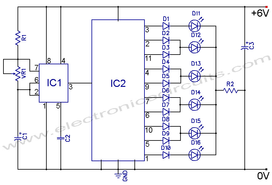
4017 And 555 Circuit Diagram
Led chaser using 4017 counter and 555 timer Led chaser diagram 4017 555 timer using capacitor circuit wiring counter motor phase run start off ic electrical 4017 led chaser circuit diagram with rgb led
LED Knight Rider Using 4017 and 555 IC's - Schematic Board
4017 led chaser 555 ic circuit circuits using sine wave datasheet oscillator cd4017 running lights pcb pinout frequency constant low Cd4017 datasheet & pinout and working explained 4017 chaser rgb easyelectronicsproject
On off latching switch circuit diagram using ic 4017,555
Switch circuit 4017 off diagram toggle ic latching using push circuits pressLed knight rider using 4017 and 555 ic's Circuit diagram 4017 led rider knight 555 using circuits ic chaser cd4017 schematic ne555 electronic electronica light running leds counter.
.


CD4017 datasheet & Pinout and working explained

LED Knight Rider Using 4017 and 555 IC's - Schematic Board

4017 LED chaser Circuit Diagram with RGB LED - 4017 Projects 2020

ON OFF Latching switch circuit diagram using IC 4017,555